Thursday, December 29, 2011

Critical Issues for Trouble-free Operation of Tube Digestion System

Hi Friends,


In earlier posts, we have already discussed about the design, engineering and operational aspects of Tube digestion system generally preferred for processing of Boehmitic Bauxite for production of alumina because of lower consumption of thermal energy. Total thermal energy consumption with Tube digestion works out to around 12 GJ per tonne of alumina which accounts for about 9 GJ/t for Bayer process (Hydrate) area and 3.0 GJ/t for calcination area.

In present post, we would like to have physical feel of Tube digestion system which may attribute in taking necessary precautionary measures while design, engineering and operational stages of the system. In this context, I would like to express my sincere thanks to one of our friends of Alumina fraternity who has shared with us two photographs clearly reflecting the pros and cons of the system being faced in one of the Alumina refineries in the World. In first photograph, the general arrangement of pipes are clearly visible where as in second photograph the nature of scaling can easily be experienced as shown below-
Both these photographs are the lessons for the designers and plant operators to take necessary precautionary measures in modifying the system while executing and operating new Alumina refinery in future.

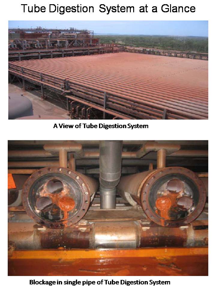
It is needless to mention that Tube digestion system is most energy efficient methodology for processing Boehmitic Bauxite over other digestion technology available so far. However, the most amicable solution for maintaining the tubes free of hard scales need to be established for the operational ease. These photographs supplements our statements and apprehensions presented in previous posts on the subject.


Request to put your views / suggestions / remarks / comments, if any.
Regards.


Kunwar Rajendra

Tuesday, December 27, 2011

Technology Driven and Equipment Oriented Units of Alumina Refinery

Hi Friends,


We have studied so far in detail the design and operating features of Alumina refinery. We have also made ourselves well acquainted with the technological advancements as well as modifications and improvements in major equipment considered for efficient operation of Alumina refinery.

In present post, we will discuss the highlights of our previous posts with more specific to technology and equipment oriented unit operations and unit processes of Alumina refinery. The process sequence of various units of Alumina refinery has been shown below-
As such, unit operations are complicated and unit processes of Alumina refinery are complex in nature because of inter dependence on the major operating and process parameters of upstream and downstream units as even minor deviations / fluctuations in process control parameters abruptly affects the plant efficiency figures. Over a period of time, lots of developments in process technology as well as improvements and modifications in equipment have occurred which has resulted in drastic reduction in overall energy consumption and raw material consumption as well ultimately improving the profitability of the plant. 

Based on our studies and experience in the field, we have clearly depicted in above diagram, the technology driven and equipment oriented process and operating areas of Alumina refinery. Selection of right technology and right equipment matching with optimized process and operational parameters will result in improved efficiency figures thereby lower capex and opex of Alumina refinery. 

Please put your views / suggestions / remarks / comments, if any.
Regards.

Kunwar Rajendra

Friday, December 23, 2011

Congratulations for the Glorious Success Beyond Our Imagination

Hi Friends,


It's a fact that we started this specialized technical blog with aggressive impulse for achieving the goal set by us within certain time frame. We could maintain the accelerated pace during our journey with our keen interests, enthusiasm and pleasure in publishing wide range of over 245 technical articles pertaining to bauxite, alumina and aluminium. Now, when we look back the trajectory of our path traveled so far , we find that we have surpassed all our targets and goals well ahead of our planned schedule without compromising on quality. It is the success of one and all associated with this blog. Till date, we have more than 31,000 members who are closely connected with this web site. Everybody deserves applaud and congratulations on this eve for bringing this platform to a new higher level of popularity. It gives me immense pleasure to be associated with this site as the founder member among the friends of bauxite, alumina and aluminium fraternity.


Now, we have to take this site to the next level covering solutions of complicated technical issues in all facets of design, engineering, execution and operation of units and plants. At this juncture, our team is working out the detailed planning for publication of forthcoming articles. Meanwhile, we solicit your views / suggestions / remarks for inclusion in forthcoming posts.


We would like to share with you this joyous moments of glorious success beyond our imagination. We seek your continued support. I take the opportunity to wish you & your family Merry Christmas and a very happy, healthy and prosperous New Year-2012. May God bring a golden feather of success on your cap in the new year.
Thanks and regards.


Kunwar Rajendra

Monday, December 12, 2011

Energy Consumption for Processing of Gibbsite-Boehmite Mixed Bauxite

Hi Friends,


In earlier posts, we have already discussed the Technology for Processing of Gibbsite-Boehmite Mixed BauxiteEnergy Consumption in Gibbsitic Bauxite based Alumina refinery and Technological options for setting up new Alumina refinery.  In present post, we will elaborate the total thermal energy requirement for processing Gibbsite-Boehmite mixed Bauxite adopting efficient high temperature digestion technology.

As such, Double digestion technology and Tube digestion technology have been rated as energy efficient high temperature digestion technology for processing of mixed Bauxite. Between these two techniques, Double digestion followed by Pressure decantation system has been successfully commercialized and operative in many plants in the World but Tube digestion technology has been adopted only in Comalco Alumina refinery, Australia. 


Comalco Alumina Refinery (CAR-1), Australia has adopted Tube digestion technology in their 1.4 Mtpa Alumina refinery. The system contains 3 slurry tubes each having 150 mm diameter fitted in a jacketed shell of 500 mm diameter pipe in 'U' shape arrangement for maintaining continuity. In this system keeping the straight length of tubes about 60 meters. In CAR, the digestion temperature is 265 degree centigrade which is attained by using high pressure steam at about 100 bar and temperature of 320 degree centigrade as heating media for Bauxite slurry in digestion. Initially, CAR Australia had all process units accept Desilication but Pre-Desilication unit was added afterwards to ensure product quality of International standard.


A new Alumina refinery owned by Ma'aden-Alcoa joint venture is planned to be executed in Saudi Arabia adopting Tube digestion technology. This project having 1.8 Mtpa Alumina production capacity is in advance stage of engineering with adoption of Tube digestion technology and planned to be commissioned by the end of 2014. This will be the 4th Alumina refinery adopting Tube digestion technology in the World. Rio Tinto Alcan owned Yarwun Alumina refinery in Australia is the 3rd operative Alumina refinery having Tube digestion technology in the World. The present capacity of Yarwun Alumina refinery is 1.4 Mtpa alumina which is under expansion to 3.4 Mtpa alumina. This brown-field expansion is planned to be completed by end of 2012 with capital investment of about US$ 1.90 billion.


The broad break up of thermal energy consumption for processing of Gibbsite-Boehmite mixed Bauxite incorporating efficient high temperature digestion technology is given below-

The above details clearly reveal that total thermal energy requirement for efficient High temperature digestion technology works out to 15.12 GJ / tonne of calcined alumina. The above figures have been arrived by carrying out detailed material balance and thermal energy balance calculations for high temperature digestion system. It is evident from above tabular data that only the digestion area accounts for over 10 GJ of thermal energy per tonne of calcined alumina which is equivalent to total energy consumption for alumina production with Medium pressure digestion technique. However, with adoption of efficient energy recovery system, it is possible to reduce the energy consumption figure by about 10% to a level of 9 GJ for digestion area which will ultimately result in overall energy consumption to the level of 14.12 GJ per tonne of calcined alumina. As per the published literature available on public domain, all existing efficient Alumina refineries in the World adopting Double digestion technology have their thermal energy consumption ranging from 15 GJ to 16 GJ per tonne of calcined alumina. This proves that calculations carried out by us  for energy consumption is in order. It also reflects that there is a scope for further reduction in thermal energy consumption in operative Alumina refineries by 10 to 15% from the present level.

It's a fact that the heat transfer co-efficient increases with increase in slurry velocity resulting in lower overall energy consumption at around 12 GJ/t alumina (9.0 GJ/t for hydrate area and 3.0 for calcination area) which makes the Tube digestion as most energy efficient process technology for processing of gibbsite-boehmite mixed bauxite. But digestion of Bauxite at high temperature at around 260 to 270 degree C in presence of lime will be pron to hard scaling on inner surface of tubes which must be kept in mind while designing the Tube digestion system for any plant for production on commercial scale. It is essential to have unique high pressure jet system for descaling the Tube digesters in order to ensure minimum downtime of the plant.

Trust, the above data / information gives clear understanding of energy requirement figures for Alumina refinery. In case you have difference in opinion on any of the above figures, please feel free to put your views / suggestions / remarks / comments, if any.
Regards.

Kunwar Rajendra

Sunday, December 11, 2011

Material Flow Balance for Residue Settling, Washing & Filtration Units

Hi Friends,

In continuation to our earlier posts, we are presenting here the Material flow balance for Residue settling, washing and filtration units of a 1.0 Mtpa Alumina refinery adopting Medium pressure digestion and associated units.
This is the typical material flow balance diagram showing main streams entering to and going out from Residue settling, washing and filtration units of Alumina refinery. The calculations have been developed with certain realistic assumptions and operating conditions practically followed in many existing Alumina refineries of the World. On similar lines, material flow balance for remaining sections can be derived.

We will appreciate your views / suggestions / remarks / comments, if any, on the presented topic.
Regards.

Kunwar Rajendra

Saturday, December 10, 2011

Material Flow for Digestion and Slurry Flashing Circuit of Alumina Refinery

Hi Friends,


In earlier post we have presented the Material flow balance for Bauxite grinding and Pre-Desilication Units. In continuation to the earlier post, we are presenting here with the material flow balance for digestion and slurry flashing circuit for 1.0 Mtpa Alumina refinery.

In this flow balance presentation, only main streams have been presented with calculated figures based on chemical engineering principles. Calculations for all these figures definitely require the fair knowledge of process circuit and related basic process parameters adopted for steady operation of Alumina refinery. 


Please put your views / suggestions / remarks / comments, if any.
Regards.


Kunwar Rajendra

Friday, December 9, 2011

Material Flow Balance for Bauxite Grinding & Pre-Desilication Units

Hi Friends,


You will appreciate the efforts put by us in exchanging views on many complicated technical issues pertaining to Bauxite, Alumina and Aluminium metal. Now, we have reached to a reasonably high level of discussions on the subject. The project engineering involving sizing of equipment as well as pipelines, material flow calculation for each stream is a must. Thus, we thought of sharing the simplified  methodology for carrying out material flow balance calculations for a typical 1.0 Mtpa Alumina refinery. 

In present post, we have just presented a sample of material flow balance for Bauxite grinding and Pre-desilication units of Alumina refinery. 

Using basics of Chemical engineering and mineral processing techniques, material flow balance for all units followed by thermal energy balance calculations for the plant may be developed by individuals for taking up assignments pertaining to design, engineering and execution of Alumina refinery. 

Hope, you will like this approach of systematic learning of process and plant design calculations for setting up Alumina refinery of any capacity.

Please put your views / suggestions / remarks / comments, if any.
Regards.

Kunwar Rajendra

Thursday, December 8, 2011

Design of Air Coolers and Water Coolers for Alumina Refinery

Hi Friends,


In previous posts, we have discussed in detail the design calculations associated with System design, Material balance and Thermal energy balance for setting up Refractory grade alumina production unit. For small capacity plant, sophisticated fully mechanized  alumina cooling facilities may not be cost effective, thus installation of semi-mechanized equipment like Air cooler and Water cooler are considered for the purpose.

In present post, we will broadly discuss the methodology adopted for sizing of air cooler and water cooler including the calculations for working out the rating of their drive motors required for their successful operation. Here, production rate of 1.00 tph Refractory grade alumina (RGA) has been considered in the sample calculations for sizing the Air cooler and Water cooler used as Primary cooler and Secondary cooler for lowering down the temperature of alumina to desired level.

Sizing of Air Cooler:-
In first step, hot calcined alumina coming out from Rotary Kiln at around 1400oC is cooled with air in Air cooler. The generated hot air is passed in counter-current direction of alumina flow through cooler. Let the temperature of alumina drops to about 300oCand temperature of air rises from 30oC to 95oC. The hot air generated is fed to the Kiln for combustion of HFO.
Heat given by alumina = 1000*0.27*(1400-300) = 297000 k.cals/hr.
Heat lost by radiation = 25% of total heat = 0.25*297000 = 74250 k.cals/hr.
If  w kg of air is passing through the Air cooler for absorbing heat,
Then heat taken by air = w*0.24*(95-30) = w*15.6 k.cals/hr.
Since Heat In = Heat Out.
Thus w*15.6 + 74250 = 297000.
Therefore, w = 14279 kg/hr.
Hence, air flow through Air cooler = 14279 kg/hr.
For design of Air cooler, mass velocity of air through Air cooler is taken as 45,00 kg/hr.m2 .
Thus, the cross sectional area of Air cooler = 14279 / 4500 m2 = 3.17 m2.
  (Ï€/4)*D= 3.17
 D = 2.0 meters.
For Air coolers, L/D =4; therefore, L = 8.0 meters.
Drive motor rating for Air cooler = 4.D= 4* (2)= 16.0 kW.

Sizing of Water Cooler:-
Calcined alumina coming out from Air cooler is further cooled in Water cooler. Here, cooling water is sprayed over rotating shell, but the contact of water with alumina is completely avoided. In this case, rise in temperature of water is less but desired cooling of product alumina is easily achieved. It is assumed that final temperature of product alumina is controlled at 90 deg.C and temperature of water rises from 30 to 40 deg.C.
Hence heat given by alumina = 1000*0.27*(300-90) = 56700 k.cals/hr.
Heat taken by water = w*1.0*(40-30) = 10*w k.cal/hr.
Since heat loss = heat gain,
Thus 10*w = 56700
Therefore, w = 5.67 m3/hr.
Thus water flow to Water cooler ~ 6 m3/hr.
Overall heat transfer co-efficient for water cooler = 50 k.cals/hr.m2.deg.C.
So, 56700 = 50*A*(40-30).
Therefore, A = 113.4 sq.m.
For Water cooler, L/D = 7.
Hence, Ï€*D*L = 113.4,
or. Ï€*D*7D = 113.4
Thus, D =2.27 m and L = 15.9 m.
Drive motor rating for Water Cooler = 4.(D)2 = 4*(2.27)2 =20.6 kW.

Trust, design calculations for sizing of Air cooler and Water cooler required for Alumina refinery have been described systematically. Please put your views / suggestions / remarks / comments, in case you have something better to share with friends of Alumina-aluminium fraternity.


If you like this article, then please press your rating as  +1   appearing at the footer of this page.


Thanks and regards.

Kunwar Rajendra

Tuesday, December 6, 2011

Method to Calculate Operating Expenses (OPEX) for Production of Alumina

Hi Friends,


In present post, we will discuss the methodology to arrive at manufacture cost (Opex) of calcined alumina with certain basic assumptions and considered issue price of input materials-


The above tabular data fairly gives the idea about the consumption pattern of various input  materials, utilities and services required for producing  calcined alumina in Alumina refinery and elaborate method to estimate the manufacture cost of calcined alumina. With indicated assumptions, the manufacture cost works out to US$174.60 per tonne of calcined alumina.  Here, the figure does not include the financing charges on capital investment. It is evident from above presented data that cost towards mining and transportation of Bauxite accounts for about 25% of manufacture cost of calcined alumina. It is advised not to take the calculated figure on face value as the manufacture cost varies from plant to plant depending on the landed price of raw materials and other variants. Please put your views / suggestions / remarks / comments, if any. 


If you like this article, please press your rating as +1  appearing in blue colour at the footer of this page.

Regards.

Rajendra Kunwar

Monday, December 5, 2011

Heartiest Congratulations for the New Record of 29,000 Viewers

Hi Friends,


Please accept my heartiest congratulations for associating yourself with our technical blog in achieving this new height of success in short span of time. I am delighted to express my sincere thanks to all of you for your cooperation and supports on every steps of our journey in stepping beyond  the prestigious record of 29,000 viewers. So far, our journey had been joyous and adventurous as well particularly in maintaining the quality standard set since start of this technical blog. Till date, we have published over 235 technical articles on this blog and will continue to add variety of new technical articles full of technical data, information and calculations in days and years to come. We are confident to honor our commitments with our valued viewers.

You must have observed and realized that each and every member of our team has made concerted efforts in improving the quality of articles in all respect. We have published many unique articles which have been developed by our team and well appreciated by our learned viewers. Many of our viewers have expressed on several occasions that such technical documents / articles / papers on such a very specialized topics are rarely available in any published literature other than this particular platform. It is an honor to our team. We are thankful for your appreciation.

On continual basis, our team will put efforts in presenting articles with enriched data, information and calculations pertaining to project and equipment engineering in particular. We will welcome and appreciate your valuable remarks / comments on published articles for further improvements. As a routine, we keep on updating our old articles with modified and latest information. Hence, you are advised to keep a track of updated old articles also. You may find something better than what you have experienced earlier. In case, you have paucity of time because of your busy schedule, just run through the articles, I am sure, you will love the article and will enjoy the content as well. Never ignore the presented articles as we have put lot of efforts for sharing these data, information and calculations with you only.

Please put your valued suggestions / remarks / comments, if any. 


If you like this article, then please press your rating as  +1   appearing at the footer of this page.

Regards.


Kunwar Rajendra

Sunday, December 4, 2011

Calculations for Mining and Transportation Cost of ROM Bauxite

Hi Friends,

In earlier posts, we have elaborated the Bauxite mining and modes of transportation of ROM Bauxite to Alumina Refinery. In present post, we will discuss the systematic approach to estimate the landed cost of ROM Bauxite in Alumina refinery. This derivation is purely based on certain factual information and a few major assumptions as described here under-

Though there are many methods to work out the mining and transportation cost of Bauxite, but the simplified method has been presented here for easy understanding. Please put your views / suggestions / remarks / comments, if any.


If you like this article, then please press your rating as  +1   appearing at the footer of this page.


Thanks and regards.
Kunwar Rajendra

Saturday, December 3, 2011

Energy Balance Calculations for Specialty Grade Alumina Production Unit

Hi Friends,

In previous post, we have briefly described the material balance calculations for a typical 3000 tpa Specialty grade alumina production unit. Here, we are presenting the sample energy balance calculations across all associated facilities like Kiln, Air cooler and Water cooler installed for calcination as well as cooling of alumina for production of 3000 tpa Refractory grade calcined alumina. On the basis of this basic calculations, it becomes very easy to arrive at estimated fuel requirement for calcination, air requirement for combustion of fuel and generation rate of flue gases released to atmosphere through stack. In the proposed system, the feed hydrate with about 10% physical moisture will be entering to Rotary Kiln at about 30oC and calcined alumina will be leaving the Kiln at about 1400oC. From hot end side of the Kiln, preheated air and furnace oil will be entering to the Kiln at around 95oC and 80oC respectively. The furnace oil temperature will be very close to its flash point while entering the Kiln through the burner.


'As is' Hydrate feed rate to Kiln = 1720 kg/hr and
Calcined alumina coming out from Kiln = 1000 kg/hr.


Energy Balance across Rotary Kiln:
Assumed composition of Heavy furnace oil -
C = 87.0%          H = 10.5%          S = 1.0%.
O = 0.10%          N = 0.20%           Moisture = 1.20%.
Calorific value = 9600 k.cal/kg.
Specific gravity = 0.92
Specific heat = 0.56 k.cal/kg.
Taking the basis of 1 kg of HFO-
Element     Composition        Moles               O2 Requirement
C                    0.87 kg        0.0725 kg. mole    0.0725 kg. mole       
H                    0.105 kg      0.0525 kg. mole    0.0262 kg. mole
S                    0.010 kg      0.0003 kg. mole    0.0003 kg. mole.

In order to ensure complete combustion of fuel oil inside the Rotary Kiln, 10% excess O2 will be required.
Thus O2 requirement = 1.10*0.0990 kg. mole = 0.1089 kg. mole
Considering 21% O2 in air,
Air requirement = 0.1089/0.21 = 0.5186 kg. mole.
N2 in air = 0.79*0.5186 kg. mole = 0.4097 kg. mole.
Now the composition of Flue gas may be derived as-
CO2 = 0.0725 kg. mole = 0.0725 * 44 = 3.19 kg.
SO2 = 0.0003 kg. mole = 0.0003 * 64 = 0.0192 kg.
O= 0.01 kg. mole = 0.01 * 32 =0.320 kg. 
N2 = 0.4097 kg. mole = 0.4097 *28 = 11.472 kg.
Thus total dry flue gas= 3.19+0.0192+0.32+11.472 = 15.00 kg.
Water vapour generated on combustion of Hydrogen= 0.0525*18 = 0.945 kg.
Mass of vapor due to moisture in HFO = 0.012 kg.
Hence total water vapour = 0.945 kg + 0.012 kg = 0.957 kg of water vapour per kg of HFO burnt.
Let x kg of HFO is required per tonne of product alumina.
Hence air requirement = 0.5186*x kg.
Mass of Flue gas = 15.00*x kg.
Mass of water vapour=0.957*x kg.


Heat Input to Rotary Kiln:-
Total heat value of HFO per tonne of product =9600*x k.cal.
Sensible heat of HFO = x*0.56*(30-0) k.cal. = 16.8* x k.cal.
Mass of water with HFO = 0.012*x kg.
Enthalpy of water vapour = 0.012*x*539 k.cal. = 6.5* x k.cal.
Enthalpy of air = 15*x*0.24*(95-0) k.cal = 342* x   k.cal.
Enthalpy of input feed hydrate = 1720 * 0.20*(30-0) k.cal = 10320 k.cal.
Therefore, total heat input to Kiln = 9600*x + 16.8*x + 6.5*x + 342*x + 10320.
Thus total heat input to Kiln = 9965.3*x + 10320 k.cals.


Heat Output from Rotary Kiln:-
Heat with dry stack gas = 15.0*0.24*(250-0) k.cal = 901 k.cal.
Enthalpy of calcined alumina = 1000*0.27*(1400-0) k.cal = 378000 k.cals.
Heat of vaporization of free moisture=170*1.08(100-30)+170*0.45*(250-100).
= 11900 + 91630 + 11475 k.cal. = 115005 k.cals.
Heat of vaporization of combined water = 0.55*1000*0.45*(1400-250).
= 284625 k.cal.
Heat of vaporization of water formed during combustion of Fuel oil
= 0.945*1.0*(100-30)+0.945*539+0.945*0.45*(250-100) k.cal. = 639 k.cal.
During operation of Rotary Kiln, substantial thermal energy is lost by radiation.
Assuming 20% of heat given by HFO is lost by radiation,
Heat loss by radiation = 0.20*9600*x k.cal. = 1920*x  k.cals.
Therefore, total heat output=901+378000+115005+639+284625+1920*x.
Thus, Total heat out = 779170 + 1920x  k.cals.
Since Heat Input = Heat Output.
Therefore, 9956.3*x + 10320 = 779170 + 1920*x.
or, 9956.3 *x - 1920*x  = 779170 - 10320.
or, 8036.3 *x = 768850.
or, x = 768850 / 8036.3 = 95.67 kg.
Taking design margin as 15%,
Specific HFO requirement=1.15*95.67 kg/t=110 kg HFO per tonne alumina.
Air requirement = 110 * 15 kg per hour. = 1650 kg per hour.
Flue gas generation rate = 110*15.0+110*0.957 = 1755 kg per hour.


Conclusions:
Specific HFO requirement = 110 kg per tonne of alumina.
Air requirement for calcination = 1650 kg per hour.
Flue gas generation rate = 1755 kg per hour.


Trust, all associated technical aspects have been covered systematically. In case you have some better method for carrying out energy balance calculations, please feel free to share with us. Your valued suggestions / remarks / comments, if any, shall be welcomed.


If you like this article, then please press your rating as  +1   appearing at the footer of this page.


Thanks and regards.

Kunwar Rajendra

Thursday, December 1, 2011

Generation Cost of Electrical Power in Coal Based Thermal Power Plant

Hi Friends,


In earlier posts, we have already discussed about the Technological Advancements in Electrical Power Generation System with regard to overall thermal efficiency and other related technical issues of Thermal Power Plants. As production of aluminium metal in Aluminium Smelters is a power intensive metallurgical process wherein the cost component of electrical power in production cost of aluminium metal ranges from 50 to 55%. Thus, the unit price of electrical power becomes the key factor for execution and operation of Aluminium Smelters. As we all are well aware that shutdown and permanent closure of many Aluminium Smelters in the World were forced in the past mainly due to high power cost.  Thus, it becomes essential to judiciously work out the unit rate of electrical power for the specific Aluminium Smelter project. In present post, we will broadly discuss the methodology to estimate the generation cost of electrical power in coal based  Thermal Power Plants clearly stating the major assumptions as outlined here under-


Major assumptions include the capital investment, specific consumption factors, overall thermal efficiency figure applicable for considered type of power plant and landed price of input materials. Here, the methodology have elaborated clearly. The power generation cost in coal based Thermal Power Plant works out to US$ 43.12 per Mega watt hour of electrical power. The above derivation clearly reveals that the cost of input fuel accounts for over 56% in generation cost of power. Thus, fuel price is the key contributing factor in improving the profitability of Thermal power plant and thereby Aluminium smelter as well.


Trust, the methodology has been clearly described for easy understanding and can be used for any capacity simply by replacing the basic assumptions with the new figure.Please put your views / suggestions / remarks / comments, if any.


If you like this article, please press your rating as +1  appearing at the footer of this page.
Thanks and regards.


Kunwar Rajendra  

Material Balance Calculations for Refractory Grade Alumina Production Unit

Hi Friends,


There is a tremendous market potential for Specialty grades of alumina all over the globe. In earlier posts, we have discussed about specifications, process route and system design for production of Refractory grade calcined alumina. 


In continuation to our earlier post, we are presenting here systematically a sample material balance calculations for a typical  3000 tpa Refractory grade alumina plant in the present post.


Basic Assumptions:
Annual production rate = 3000 tonnes per year.
Annual operating days = 150 days per year.
Daily operating hours = 20 hours per day.
Input feed material = Chemical grade Hydrate.


Material Balance Calculations:
Thus hourly production rate = 3000 / (150*20) = 1 tonne per hour.
Dust loss through stack = 0.50%.
Miscellaneous handling losses = 0.50%.
Hence dry hydrate feed to Kiln = (1.0*156/(0.99*102) = 1.55 tph.
Moisture in feed hydrate to Kiln = 10% (w/w) - assumed.
Thus Feed hydrate to Kiln = 1.55/0.90 = 1.72 tph.
i.e. Output hydrate from Rotary vacuum filter=1.72 tph.
Solids in feed slurry to Filter=45%.
                                                              290
Specific gravity of feed slurry = ------------------ = 1.55
                                                     242-1.22*45
                                                   1.72
Feed slurry flow to Filter = ---------------- = 2.47 m3/hr.
                                              1.55*0.45
Wash water to Filter = 1.0 m3/tonne of Hydrate.
Total wash water = 1.0*1.55 = 1.55 m3/hr.
                                                                                                    290
Specific gravity of Kiln feed Hydrate with 10% moisture = ---------------- = 2.19
                                                                                             242-1.22*90
Thus volumetric flow of Hydrate from Filter = 1.72/(0.90*2.19) = 0.87 m3/hr.
Therefore, total material flow to Filter = 2.47+1.55 = 4.02 m3/hr.
Flow rate of filtrate = 4.02 - 0.87 = 3.15 m3/hr.


The above calculations broadly cover the material balance from hydrate filtration to calcination unit  for production of 3000 tpa Specialty grade of calcined alumina.
Please put your views / suggestions / remarks / comments, if any.


If you like this article and find it useful, then please press your rating as  +1  appearing at the footer of this page.


Thanks and regards.

Kunwar Rajendra